This post is about ultra low power motors you can build yourself with a little help from a 3D-printer. Put inside a glass display it will run for years.
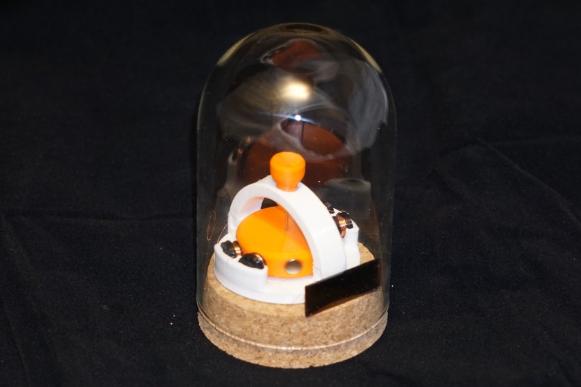
The motor is not intended to drive anything, how could it at such low power… just to put this into perspective: if you put a drop of cold water in your hand and let it warm up, the energy transferred to the water could run the motor for hours. I hooked mine up to an amorphous silicon solar cell salvaged from a solar toy and with a super capacitor as an energy storage it runs 24/7 just from ambient light in a room, no direct sunlight necessary.
It can also run from various other low power sources like a peltier element (TEG) or any home-brew battery like potato battery or even an aluminium-saltwater battery: I had one of the motors running for three months on just aluminium foil and salt water before the battery shorted out due to corrosion.
Design Process
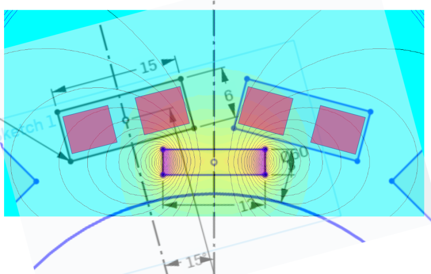
This all started when I saw an interesting video on youtube by lasersaber. Since he came to the design of the pulse motor by experimentation I thought I may be able to improve it even more by taking the engineering approach and doing a simulation of the magnetic field to find the best ratio of magnet to coil size. I simulated the magnetic field of a cylindrical magnet with femm a free FEA simulation tool and overlayed the ideal position of the coils in power point (final result shown below). It turned out that he had it not quite right in his initial deisgns (coils too thick) but then came to the same conclusion in later designs as can be seen on his blog it just took him a few months to figure this out while the simulation approach only took me like 20 minutes. Engineering skills for the win!
Just a little motor theory on how a pulse motor works (and how the simulation shows this is a ‘good’ design):
unlike other motors a pulse motor does not have a continuous torque nor a continuous current and is therefore useless for higher power applications but it is a great demonstration of the physics at play and very easy to build. The trick is to apply a voltage to the coils only for a brief moment when the magnet is at the ideal position to generate the maximum amount of force. This moment is shown in the image above:the magnet is exactly between two coils. The current in the coils flow in opposite directions. The image also shows that the field drops quickly when going away from the magnet which means any current flowing close to the magnet produces way more force than the current at the back of the coil which is why a thinner coil is more efficient than a long coil as it generates more force per current. The part of the coil where the current returns (most left and most right purple squres) will generate a force in the opposite direction except if the magnetic field also flows in the opposite direction i.e. is on its returning loop. You can see from the field lines that this is exactly the case in the chosen geometry of the coils: in this case the returning current meets the returning magnetic field and generates even more force even if it is way less then the two central parts of the coils. Say the current in the windings closer to the magnet flows into the screen and the magnetic north pole faces the coil then the Lorentz force produced points to the left, tangential to the rotor making it spin counter clockwise.
Adding more than two coils increases the force but in theory should not increase the efficiency but in reality a more symmetrical design runs more smoothly because the parasitic foces generated from imperfections are balanced out making the rotor run more smootly.
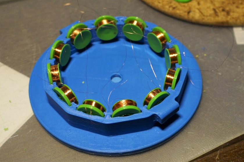
The geometry can be scaled to any size. The first motor I built has six 12mm magnets and 12 coils but since winding these coils is a very tedious process I improved the design and made it smaller with only four coils. Compared to the design done by lasersaber mine is much easier to print and assemble.
How it works in practice
The theory sound solid but how do you produce a current pulse just at the right moment? Normal motors use sensors (or back EMF) to sense the rotor position and with some advanced switching electronics apply the right current at the right time. This could be done for this motor as well but the electronics would use way more power than is required to run the motor itself.
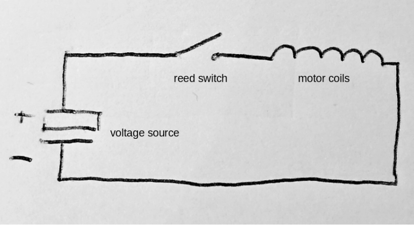
The trick here is to use a reed switch which closes when a magnet is close to it and opens if the magnetic field is too weak so it acts both as a sensor and a switch at the same time. The rotor has the magnets and if the reed switch is poisitioned just right a current pulse is applied in the right moment. It can be tricky to get it just right and the use of an oscilloscope can be very helpful but it can be done without one. The schematic diagram of the circuit looks like this:
Build instructions
If you want to build your own little pulse motor here is what you need:
- 3D printed parts (download from thingiverse)
- Neodymium magnets
- 12mm diameter, 3mm thick for large design
- 6mm diameter, 2-3mm thick for small design
- 3mm diameter for holding pin
- Reed switch, the smaller the better (aliexpress has some)
- Thin enameled copper wire (I used 0.05mm wire)
- Sowing Needle for rotor shaft (get a set)
- Sapphire/Corondum bearing or flat Sapphire glass (aliexpress)
Optional:
- Amorphous silicon solar cell (the reddish brown ones)
- Supercapacitor to match solar cell voltage, 1F-2F capacitance
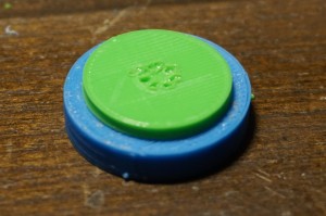
After you collected all the items and printed all the parts and made sure everything fits together start off by winding the coils. The bobbins are made out of two parts. Put them together to form a bobbin and use a solderin iron set to 200°C to melt the pin and weld it at the back of the coil. You can also use superglue.
The tool to wind the coils is also provided in the 3D files. I used a brushless motor clamped in a vice to wind the large coils as this is much faster but an electric drill works just as well. Leave a length of about 10cm of wire at the beginning and the end of the coil and secure them with tape. A drop of superglue on the coil before winding the last few rounds helps to keep it from unwinding.
Try to wind it as nicely packed as possible but do not put too much strain on the wire. I found that a good way to do it is to hold a paper towel in your hand and run the wire through it, applying slight pressure on the towel and guide the wire to where it needs to go. Wind a few extra coils as spares in case one is bad or the wires break during the assembly. The winding direction is not important but it has tho be the same for all coils!


Now mount the coils into the base with both wires of each bobbin coming out the top. To connect the wires twist them together and solder them by passing them through a liquid ball of solder on the tip of the soldering iron. It helps to set the temperature to 400°C or even higher and use fresh solder on the tip for each wire. To get the enameled copper wire to take the solder can be frustrating at times, believe me. In order to get the current to flow clockwise in one coil and counterclockwise in the next (as explained above) connect the end of the wire of the first coil with the end of the second one, then the beginning of the second one with the beginning of the third one and so on generating an alternating pattern but do not connect the beginning of the first coil to the beginning of the last: that is where the reed switch and the supply voltage comes in. Trim the soldered wires and tuck away the solder joint somewhere it will not come in contact of the rotor.
To test if the polarity of all coils is correct there is a simple trick: connect a AA battery or any power supply of choice to the open circuit. Tin the end of the wires first and maybe check the resistance with a multimeter (depending on the wire used it is a few hundred ohms to a few kilo ohms). With the batter connected and the current flowing each coil acts as an electro-magnet. Holding a small magnet in front of each coil the magnet will indicate the field direction which has to be alternating north-south-north-south-… when going around the motor. This rule applies for both motor designs even though the small one only has four coils.
Next prepare the rotor. Put the magnets in and seure them with some glue. The orientation of the magnets has to be the same for all of them! To check this take a stack of magnets and check if each magnet is facing the same way.
Stick a needle into the hole in the center, use a small drill if it does not go through but make sure you do not drill in an angle! Now try to spin the rotor on a tabletop and see if it runs smoothly without too much wobbling. Depending on how well calibrated your 3D printer is it may wobble quite a bit. You can try to bend the needle a little to make it wobble less but if it is just too much you may need to align and calibrate your printer first.
Before securing the needle with some more glue it needs to be adjusted to the correct height. To be able to do that the bearing needs to be placed into the base. If you got a ruby bearing (or made one as described in my last post) mount it in the center using hot melt glue or plasticine (or print yourself something). If you want to use a sapphire glass (a piece of normal glass like a microscope slide works at first but wears out very quickly, like within a few weeks and then grinds down the needle so really not recommended) you need to put a small magnet under it, like a 4-6mm diameter, 2-3mm thick magnet to always keep the needle at the center. That is what the center hole was designed for. Secure the magnet with some glue then put the glass in.
Now mount the rotor on top of the bearing and adjust the needle height so the magnets align well with the coils (center height should be the same).


You can test how well the rotor spins by holding it in place with a magnet mounted just above the top of the needle. I used an adjustable arm for that as shown in the picture.
To mount the arc with the adjustable holding-pin the needle has to be trimmed. Cut it to length using some strong side-cutter becauase needles are made of hardened steel. The length should be such that there is a few millimeters of space between the top of the needle and the arc.
Mount the small magnet to the adjustable pin and glue it. Put the pin in and adjust it until the rotor stands straight but the needle does not touch the magnet of the pin: there should be a gap of about 1-2mm. Now the rotor spins very easily and it can be spun up by blowing on it. If you own an oscilloscope, hook it up to the two wires and see how it generates an AC voltage. You can also hook up a AA battery (or several in series if your coils are in the kilo ohms) and try to apply short pulses by hand to see if you can get it to spin.
To make it work is now just a few steps away. Take the reed switch and shorten the leads a little. Actually to trim them down to 1mm is key to run the motor at very low speeds but with such short leads it becomes very difficult to solder the wires. Wrap one of the copper wires from the motor around one of the leads a few times then solder it (you may want to tin the copper wire first). Take another piece of copper wire like 10cm long and solder it to the other lead of the reed switch.
Solder the two wires that are now left to some thicker wire to make it easier to experiment then hook them up to a battery. For the small motor made with 0.05mm wire a voltage of 1-2V is plenty, for the large motor with the same wire 4-10V is more adequate. To check if all is workin you can use a small magnet and hold it close to the reed switch and the rotor will twitch.
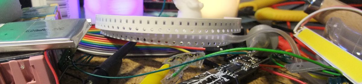
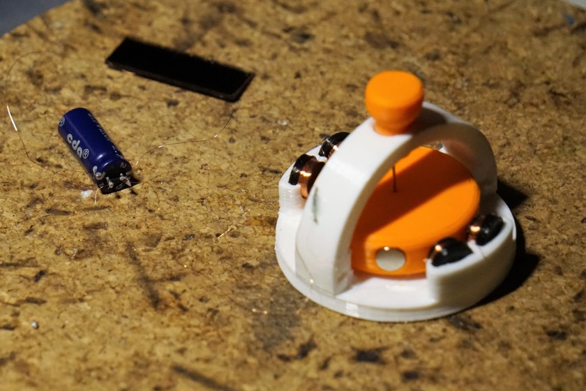
To find a good position for the reed switch slowly move it towards the rotor and a soon as you see a reaction try to move it left and right to find a spot where the motor starts to spin up. To find this position is quite easy but finding the spot where it runs at minimal power is a lot harder. I use scotch tape to fix the switch in a position and only glue it after I am sure it is a good spot. The fotos show where this sweetspot was on my motors, both the small and the large one. You may notice I used a tiny reed switch on the small motor, I do not know what type it is nor where to get it, I got it from a leftover pile of an experiment at work. You may also notice the capacitor ant the diode on the reed switch of the large motor: this is a so called snubber circuit I use to reduce voltage spikes that made this switch get stuck from time to time.


Once you get the hang of it it becomes easier to adjust the position. But not only the position but also the orientation of the switch is important: it must be positioned so it catches just enough of the magnets field to switch on but only very briefly. To tune this without the help of an oscilloscope can be difficult but not impossible and just takes a lot longer. First you have to find approximately the right distance, then the best position and orientation and finally tune the distance at that position and mabe fine tune some more. The right distance and approximately the right position is where the motor spins up on its own. Once you found that stop the rotor and adjust the position of the reed switch such that that the magnets get a push when moved exactly between two coils but not if just slightly (more than 2mm) off from that position. Once you get that to happen you are already very close to the sweet spot and if you do not want to go record-breaking low power then it is good enough. However if you want to go as low as it can go you need to reduce the voltage of the power supply and tune further until it spins very very slowly without stopping. I got it as slow as one rotation taking over 10 seconds. Measuring the actual power also helps, see below on how to do this correctly.
Fine Tuning and measuring power
To measure the point where the reed switch is turned on it is easiest to measure the voltage over the switch with an oscilloscope. Since the oscilloscope probes are magnetic an additional wire has to be soldered to the switch so the probe can be placed further away from the motor. The ideal point for the switch to turn on is when the voltage generated from the rotor is at the lowest point. The voltage is shaped like an ‘m’ as shown in the screenshot below. The part where the voltage is zero is where the switch is on. The measurement was taken on the small version of the motor but it looks similar on the large one. Notice how the voltage drops almost to zero just before the switch is turned on showing the voltage generated by the magnets is almost the same as the voltage applied to the motor. It can also be seen that there is some asymmetrical behaviour coming from a not perfectly symmetrical rotor: not all magnets may be the same strength or exactly at the same distance from the switch making it turn on or off at different times. When the switching behaviour is as shown the position of the switch is very good, if it is wrong the ‘zero voltage’ spike is off center from the ‘m’ shaped waveform resulting in additional current draw. The most important thing is to have the switch turn on at exactly the lowest point, not too soon, not too late and not too long. To optimize the power consumption even more the switch would need to be moved further away so the on-state is as short as possible. It is also ok if the switch does not turn on for each magnet but only for two or even just once per rotation, that is when I got the best results for low power but if you want the motor to run reliably for a long time that is not ideal as it can stop running if the rotor moves just a tiny bit away from the switch over time.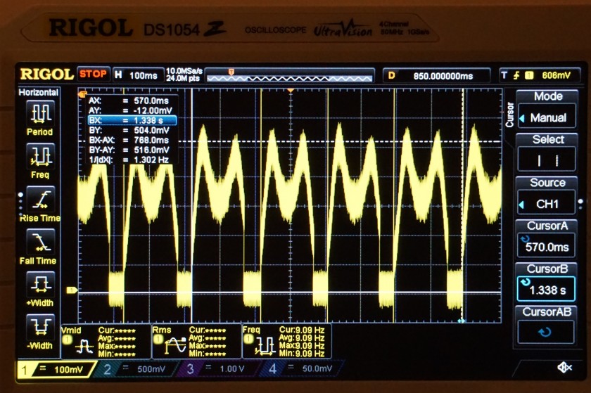
To measure the power consumption two multimeters are required: one to measure the voltage and one to measure the current. At low speeds the current spikes for a short time and is then zero for a long time. In the measurement abofe with the motor running at 1.3 revolutions per second (1.3Hz) the on time for each pulse is less than 50ms which a multimeter does not handle well. The current has to be averaged with a capacitor and a resistor so it is constant. I use a 1000µF capacitor and feed the current to the capacitor through a 1k resistor resulting in a 10s time constant meaning the pulses are averaged over about 50 seconds (five times the time constant). The voltage is fed to the motor from the capacitor so its voltage is the input voltage to the motor (not the voltage of the power supply connected to the resistor). It takes a few minutes until the everything is stable: the rotation speed, the voltage and the current and that is when the power can be measured.
The limits of low power
I was curious about the efficiency of the motor and what the minimum power would be if the motor was just tuned right. First I just played around with the alignment of the reed switch and then lowering the supply voltage as low as possible without the motor stopping. I got it as low as 60nW at one point. The second small motor I built was not able to run at a power below 500nW so I must have either tuned the first one better or hit some kind of a sweet spot.
But is this the lowest it can go? What power is actually lost in the friction of the bearing and air friction of the rotor? Lasersaber claimed in one of his videos that he got it running at just 4nW which is more than ten times less than my best effort and I simply could not believe this was even possible so I had to know if my design was just more inefficient or if he cheated.
The power lost in the rotor are from air friction and friction in the bearing. The friction of the needle bearing I approximated as a tiny cylinder rotating on a flat surface because the needle point will not only touch on one atom. The reality is somewhat different but assuming there are two solid surfaces touching there will be rigid body friction which generates a constant drag at low speeds. A constant drag means that the loss is linear to speed since power is force*speed so if the needle bearing dominates the friction the rotor losses should be linear. Now the air friction losses on the other hand are not linear to speed but squared with the speed (for low speeds) and even cubed with the speed at higher speeds. Since the rotor spins at low speeds a laminar air flow can be assumed but let’s not only assume, let’s measure.
In order to get the losses by friction (both air and bearing) the energy lost in the rotor can be measured. To do this we can calculate (approximately) the moment of inertia of the rotor which is it’s ‘rotational mass’. I measured the weight of the rotor and the magnets and calculated the corresponding moments of inertia:
magnets (4.1g) rotating at a radius of 14mm: J = 8e-7 kgm^2
bare rotor (2.3g without magnets) of a radius of 15mm: J = 3e-7 kgm^2
The experiment was to speed up the rotor by blowing on it and then measure the speed at certain intervals. The speed was measured by measuring the voltage over the reed switch with an oscilloscope (like shown in the above screenshot) which gives very accurate readings. I put this all into calculation sheet, calculated deceleration from the speed and with the deceleration known and the moment of inertia known the power loss at each measurement point is also known. It shows very nicely a square function of power loss. What can also be checked if the drag coefficient is constant or proportional to speed. The graph shows that for speeds above about 1Hz it is almost constant and then increases meaning the drag force no longer depends on rotation speed and the bearing friction dominates. With the drag coefficient being constant for speeds above 1Hz it means that the assumption of laminar flow is correct.

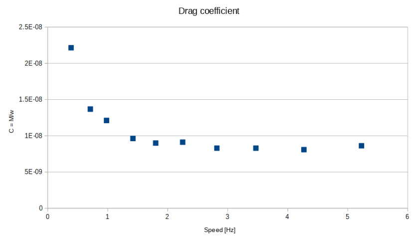
Ok with the theory and assumptions veryfied what does this mean now. It means that at speeds larger than 1Hz the air friction is the dominating factor of losses and below 0.5Hz the needle bearing starts take over and losses become very small.
But what’s important is that the minimum power required to keep it rotating at about 0.5Hz which is quite slow already is still 150-200nW. Now with the drag being dominated by the friction of the bearing the power decreases now linearly with the speed so at 0.1Hz or one rotation every 10 seconds the power required is 30-40nW.
At 6Hz the measurement is more accurate though and at this speed the losses are about 13µW. The power required to run the motor at this speed I measured to be 24µW so the efficiency of the motor is just above 50%. Not really great but for the simple design it is not too bad. I honestly would have expected it to be below 30%.
The bottom line is that no matter what a power consumption below 10nW is simply not possible to achieve with this design. To make it possible much more precise parts would be needed, a heavier rotor that can store more energy and therefore go to even lower speeds and maybe a harder rotor material like a very pointy ceramic tip. The light weight rotor is at one point locked to the earth magnetic field and cannot escape it if it is too slow so higher speed or a heavier rotor would be needed.
Here are a few measurement results just to show what some tuning of the reed switch can do. Three measurements were taken at the same speed after tweaking the power almost dropped to half.
6.2hz, 16uA 1.5V = 24uW
492mHz, 4uA, 160mV = 0.64uW
492mHz, 3.7uA, 151mV = 0.55uW
492mHz, 3.2uA, 117mV = 0.37uW
320mHz, 3.0uA, 90mV = 0.2uW
85mHz, 1.7uA, 35mV = 60nW

Are your STL files in mm or inches? I 3D printed the bobbins and they are quite small (0.35 inches diameter), almost too small to work with?
LikeLike
The STL files are in mm. Yes it is small. You can scale it to 2x and use bigger magnets if you want or print the bigger version (the one I printed in blue).
LikeLike
OK, I think I am going for the larger with a minor modification. I want to set it up with 4 magnets and 4 coils, like the smaller one. That will allow me to test it without having to build so many coils. I think that would work, correct?
LikeLike
It sure works with four coils, it would even work with just one at the expense of efficiency.
LikeLike