Something I had on my radar for many years was to design and build a small line follower robot. I took the challenge up a notch by constraining myself to these design rules:
- no 3D printed Parts
- has to fit on a 5x5cm PCB
- BOM cost of less than 10$
- PID regulated
- regulator must be adjustable using Potentiometers
- slick mechanical design
- must look cool
constraining the BOM to less than 10$ was a major challenge. Digging around on banggood.com for inspiration I did find really small ball bearings and motors. I wanted to use small and cheap vibration motors driving the wheels directly from the shaft. Next was to find a suitable rubber to make up a tire. An O-ring of course. The ones used as damping elements in keyboards perfectly fit on the bearings and you can get 150pcs for about 3 bucks.
The microcontroller was a given, it had to be the STM32F030. Got a ton of those around from the LambdaNodes project . The optical sensors chosen are the small QRE1113. As for switches for the motors the first choice was two NFETs but since NPN transistors are more robust when it comes to ESD I went with the latter.
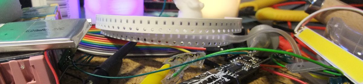
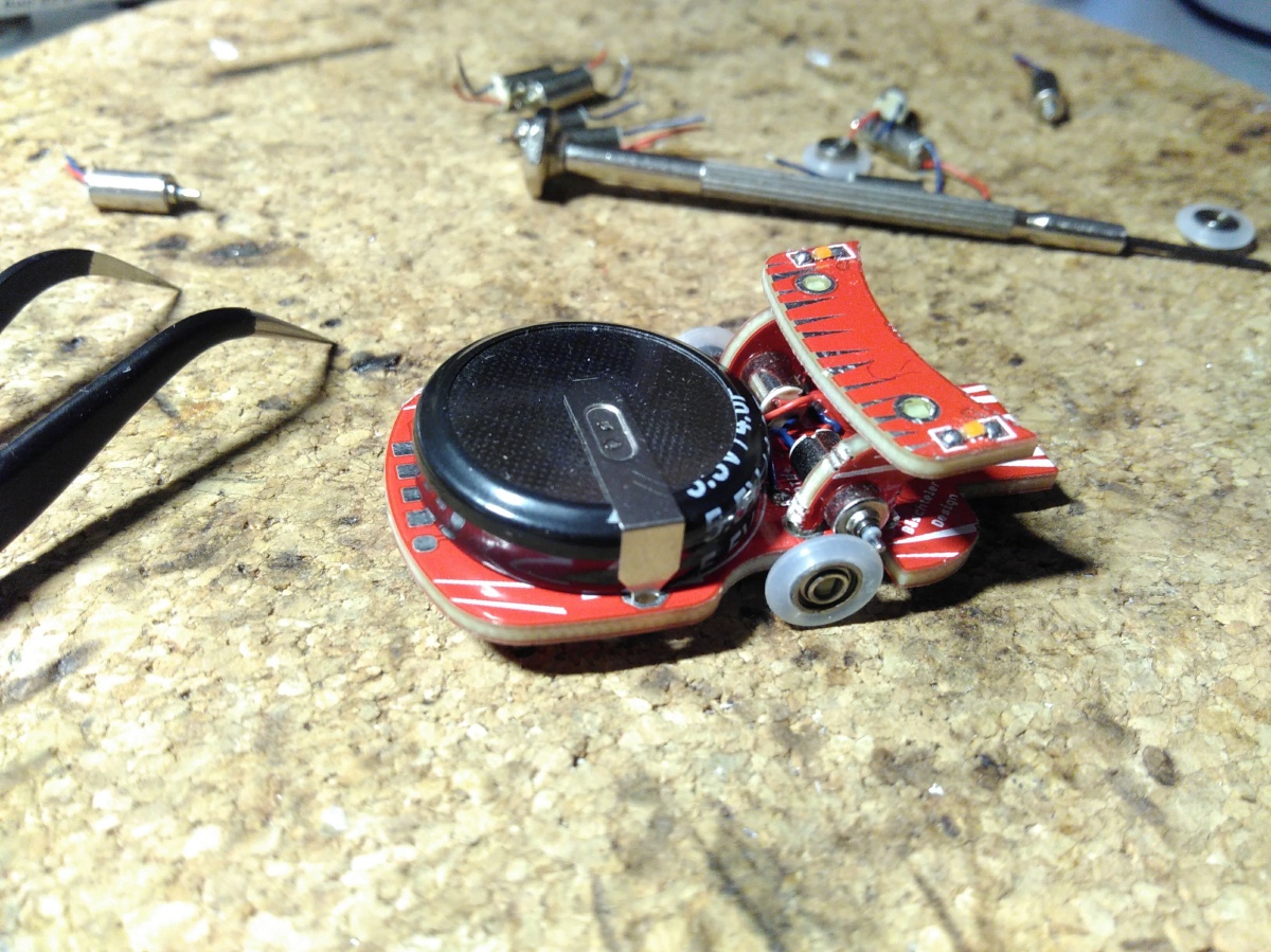
As you can see in the fotos of the first prototype the initially planned power source was a supercap. Turns out these Chinese ‘4F’ caps actually are more like 1.5F caps and so the calculated run-time of about 1 minute was reduced to just 25 seconds. Good thing I planned to use a small LiPo battery as a backup by including a TP4054 charger IC in the initial design. Works a charm and delivers power for a long time.
To charge the cap/battery there is a built-in USB plug which needs some extra solder on the power pads as the 2mm pcb thickness needed for a reliable connection did not fit the ID of the bearings so I had to compromise.
As far as cool looks go I just had to add a rear spoiler and some LEDs. The two ‘side walls’ that I initially just designed to hold the motors in place double up to hold up the spoiler. The switch conviniently fits under there and since everything is made from PCB I could even run current through to light up the LEDs on top. Nice!
Everything was designed in Eagle first then exported to DXF and imported into Onshape to see if it all fits as planned which of course it did not – forgot to factor in the 3rd dimension when it came to the distance between the wheel and motor axle.
When the PCBs finally arrived I was positively surprised on how well everything fit. The press-fit for the bearings is close to perfect and the 4mm diameter motors snuggly fit in the side parts. The motor alignment is a little tricky because the position can only be adjusted as long as the solder is kept hot and liquid.


Before getting started with the firmware I decided to try and set it all up using CubeMX for STM32 and a new develpment environment – ‘System Workbench for STM32’. They go well together but I was struggling with some of the interrupts and how CubeMX forces you to arrange the code. Found my way through most of the issues except that damn ADC interrupt that just refuses to work. I have it running no problem when not using the HAL drivers. Finally gave up upon it and just went with polling the ‘End of conversion’ flag.
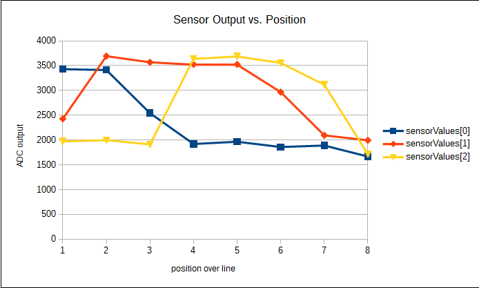
Getting the correct algorithms to detect the line and tweaking the regulator were tedious work. PID regulators work best for LTI systems (linear time invariant) which this system of course is not. It can still function in a ‘linearised working point’ but since the motor drive cannot be put in reverse to actually brake the whole system is not very linear: accelerate fast, decelerate slow. And even the acceleration or motor torque seems very non-linear. So I started experimenting with squred or even cubed proportional feedback and got some good results but then found that I can get much better results (and less integer overflows) by making the line position detection non-linear. The algorithm was found by trial and error on what works best and took quite some time. The only good way I found so far is to detect when the center sensor looses sight of the line and the line moves away from the outer sensor – which results in the line position algorithm, a weighted sum, to report the line actually moving back to the center. The part I do not like about the algorithm is that for now it has to deal in absolute readings so it may not work well on all robots. Here are some not-so scientific measument results (bäschteler style):
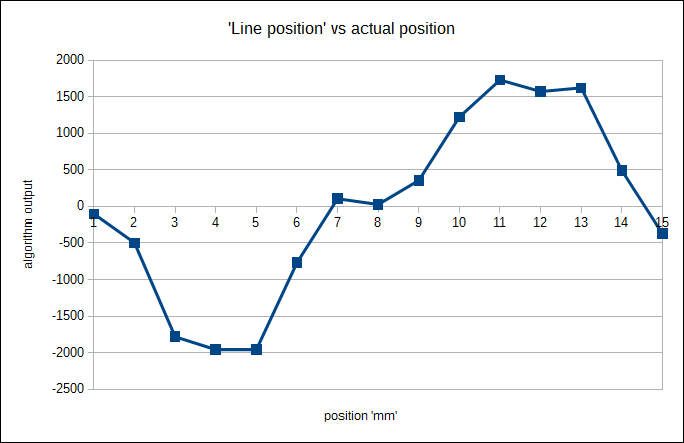
The second graph shows how the ‘line position’ output of the weighted sum algorithm actually idicates the line moving back to the center instead of away. For a PID to work best this graph should be a more or less straight line from the bottom left to the top right. This kind of ‘error function output’ results in a lot of oscillation.
The tweaked algorithm tries to detect when the line is at the outer edges and reporting a maximum error when it does. For the test robot this works just fine. There are a lot less oscillations if the regulator is set just right and the robot actually can most of the times find its way back to the line if it looses sight of it. This is done by keeping the error to a maximum (or negative maximum) when the line moved out of sight in a sharp turn for example.
An unsolvable problem is the lack of brakeing ability. Of course a fully fledged motor driver with a proper H-bridge could solve that but there is not enough room without changing to 0603 components. Also GPIO pins are scarse, I would need to sacrifice the debug pins. But hey, it works fine with just a single transistor although it probably could go a little faster if brakeing at sharp corners would be possible, but then again, maybe not. For the size and simplicity of the robot it is plenty fast.
The speed needs to be tweaked to the lowest point before it does not move at all. That is where it moves around the track smoothly. If there are any sharp turns in the track this is especially true so it does not overshoot and loose the line. The speed can in fact be increased when the regulator is put more to the limit by cranking up the integrator as well as the proportional part. It then moves fast and violently over the track.
This video shows how well the robot can navigate around a track printed on a A3 sized paper using different regulator settings:
I am very happy the way the design turned out and also how well it works. For the next round I ordered different motors with hopefully higher resting torque as well new PCBs with some minor issues removed. Also I hope that the manufacturer will not remove the silk screen writing on the spoiler this time.
You can find all the design files on my git repository. If you would like to get a kit with all the components drop me a message and I will see what I can do.

One thought on “Get In Line – tiny line follower robot”